Nikken Kosakusho Works v Pioneer Trading Company
| Jurisdiction | England & Wales |
| Judge | Mr Justice Mann |
| Judgment Date | 08 October 2004 |
| Neutral Citation | [2004] EWHC 2246 (Ch) |
| Court | Chancery Division |
| Date | 08 October 2004 |
| Docket Number | Case No: HC03C01963 |
[2004] EWHC 2246 (Ch)
IN THE HIGH COURT OF JUSTICE
CHANCERY DIVISION
Royal Courts of Justice
Strand, London, WC2A 2LL
The Honourable Mr Justice Mann
Case No: HC03C01963
Mr John Baldwin QC and Dr. Michael Tappin (Instructed by Messrs. DLA, Leeds) appeared on behalf of the Claimants
Mr Iain Purvis and Mr Benet Brandreth (instructed by Messrs. Field Fisher Waterhouse) appeared on behalf of the Defendants
Approved Judgment
Hearing dates: 17 th-21 st, 25 th,28 th May 2004
I direct that pursuant to CPR PD 39A para 6.1 no official shorthand note shall be taken of this Judgment and that copies of this version as handed down may be treated as authentic.
Introduction
This action started life as a claim for infringement of a UK patent no. 2,322,316 ("the patent") which relates to a milling chuck, as a claim in passing off and as a claim for infringement of copyright. During its subsistence it became refined to claims relating to the patent. There was a counterclaim for a declaration of non-infringement of the patent and for revocation of the patent. Over a period of time various aspects of the claim were successively abandoned, and by the time of the trial the action was in substance a trial of the counterclaim. By the time of final speeches there was no opposition to the claim for a declaration of non-infringement, so the issue which now occupies centre stage is the defendants' claim for revocation on the grounds of lack of novelty and obviousness. The first claimant (a Japanese company – "Nikken") is the patentee under the patent. The second claimant is its UK subsidiary. The defendants are respectively a Japanese company and its German subsidiary, both trading in engineering tools; it will not be necessary to treat them separately in the course of this judgment and I shall call them both "Pioneer".
The invention
The invention said to be disclosed in the patent is an improvement to high speed tool chucks. These are carefully manufactured pieces designed to hold a cutting tool used for high speed precision cutting or drilling. One end fits on to the machine tool itself, and the other holds the tool. The chuck, and thus the tool, is then rotated at great speeds – 15,000 rpm or so. The tool has to be held securely. The first invention is said to improve the grip on the tool. The second is said to improve sealing of certain parts against debris, and damping of vibration.
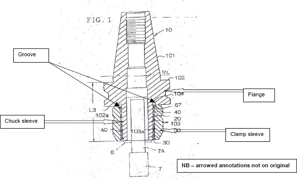
The invention is shown in a cross-section diagram in the patent thus:
In this diagram the orientation is such that what appears at the top is the part that fits into the spindle of the machine tool; and the cutting tool is fitted into the bottom – its shaft is shown as 7A. Working from the top of the diagram, there is first a tapered portion which fits into the machine itself where it is held firm. This has an obvious taper, and it ends in a thick flange (102). Below the flange (in the orientation in the diagram) is a narrower sleeve (the chuck sleeve, (103), which holds the tool. The shaft of the cutting tool fits into a collet (8), which in turn fits into the chuck sleeve. This has to be gripped very firmly so that the tool can perform its function. The grip is achieved as follows. The outer surface of the chuck sleeve is tapered towards its end ie it narrows towards the bottom of the diagram in the above orientation. Over the outside of that sleeve is fitted a metal cage or sleeve (20), tapered like the chuck sleeve, and which contains needle rollers inclined so that they are not in line with the longitudinal axis of the chuck sleeve. They protrude through the roller sleeve, so that on one side they engage with (by rolling against) the chuck sleeve. On the other they engage with (by rolling against) a clamp sleeve (50), which fits over them. This enables that clamp sleeve (which again has a taper matching that of the chuck sleeve) to rotate against the roller sleeve, and this in turn allows the clamp sleeve to be "screwed down" towards the flange of the chuck so as compress the chuck sleeve which grips the collet which in turn grips the tool shaft.
Thus far the description of the features of the chuck coincide with prior art. The invention is said to comprise two aspects of the chuck shown in the diagram. The first is a groove which is cut into the flange at the base of the sleeve. It is shown in cross-section at 104 in the diagram above. The second is an elastically deformable O-ring which fits into that groove and against which the clamp sleeve and needle roller cage are screwed down.
The purpose of the first aspect (claim 1 in the patent) is to improve the grip on the tool shaft. It is said that the amount of grip can be ascertained by measuring the internal diameter of the clamp sleeve in its clamped and unclamped states. The greater the reduction in diameter, the greater the grip; and the more the diameter can be reduced along the length of the sleeve, the greater the overall grip. It is said that the effect of this aspect of the invention is to lengthen the effective length of the chuck sleeve, and to increase the extent to which the internal diameter can be reduced at the flange end, thus increasing grip at that flange end. Various things can be done at the other end (the tool end) to increase grip there; this aspect of the invention achieves a similar effect at the flange end, increasing uniformity of grip along the length of the tool shaft.
The purpose of the second aspect (the O-ring – claim 8 in the patent) is to improve damping and to form a seal. At the flange end of the roller cage there is a retainer ring. Its inner surface supports the needle roller sleeve. When the clamp sleeve is fully rotated down (to fix the tool) the outer surface of the outer surface of the retainer ring is pressed against the O-ring. This is said to reduce "chatter" and absorb other vibrations; those vibrations would otherwise adversely affect accuracy of machining. It is also said to provide a seal which prevents dust and cutting fluid from entering the roller cage and the groove.
The true construction of Claim 1 the patent
Before moving on to consider the attacks on the patent, it is necessary to deal with a question of construction that arises out of it, because certain questions of anticipation turn on the point. That question arises out of the terminology used in claim 1 of the patent, which is the claim which encapsulates what I have described as the first aspect of the invention. It describes "A chuck comprising" various features, including the chuck sleeve and the clamp sleeve, and then adds the following words:
"wherein movement of the clamp sleeve in a direction which includes an axial component with respect to the chuck sleeve is operative to urge the chuck sleeve in a substantially radially inward direction in order to reduce the internal diameter of the chuck sleeve, and wherein an annular groove of predetermined depth is formed in the end surface of the flange distant from the shank portion such that the radially inner surface of the said groove is contiguous with the outer circumferential surface of the chuck sleeve." (emphasis supplied).
The relevant words are underlined. They are the words which describe the depth of the groove, and are the only words in the Claim which purport to do so. It is obvious that taken by themselves, and at face value, they do not contain any objectively ascertainable measurement or criteria by which one can determine the depth (or indeed the width) of the groove in question.
The rival contentions of the parties as to the meaning of the words is as follows:
a) Pioneer says that the words mean what they say – a "groove of predetermined depth" means any groove whose depth has been decided in advance by the creator or designer of the groove.
b) Nikken say that that construction is unrealistic. It says that on its true construction this Claim bears one of two alternative meanings. First, it means a groove of sufficient depth to achieve the object of the invention. Alternatively, if that is not right, then it means a groove of "approximately 3–5mm" in depth because in this respect the patent acts as its own dictionary. In putting forward these constructions Nikken relies on what appears in the specification as forming important material for the construction of the claim.
The significance of this dispute arises out of the reliance by Pioneer on a piece of prior art, namely a drilling chuck called (in the parlance of this case) "Daishowa 1". I shall have to deal with the detail of this prior art in due course, but for the present it is sufficient to say that this chuck has what might be called a groove in what might be said to be in the same contiguous position as the groove in the invention. If Claim 1 refers to any groove whose depth is predetermined, then subject to a question as to contiguity Daishowa 1 can be said to manifest such a groove, and it therefore anticipates the invention and invalidates the patent in this respect. On the other hand, if Nikken's arguments are correct, there is no evidence that the groove in Daishowa 1 has the effect of the groove in the invention, and it does not appear to be 3–5mm in depth, so there is no anticipation.
In determining this point I bear in mind the principles of construction set out in the authorities and in Article 69 of the Protocol on Interpretation. So far as the latter is concerned, it requires me to eschew literalness and to eschew using the claims as mere guidelines. I have to interpret the patent as:
..."defining a position between those extremes which combines a fair protection for the patentee with a reasonable degree of certainty for third parties."
To continue reading
Request your trial
-
Generics (UK) Ltd Trading as Mylan v Warner-Lambert Company LLC
... ... each of which the leading judgment was given by Jacob LJ, namely Nikken Kosakusho Works v Pioneer Trading Co [2005] EWCA Civ 906 , [2006] FSR 4 ... ...
-
Warner-lambert Company Llc v Sandoz Gmbh and Others
... ... Down Judgment of WordWave International Limited Trading as DTI 165 Fleet Street, London EC4A 2DY Tel No: 020 7404 ... the principles established in such cases as Nikken Kosakusho Works v Pioneer Trading Co [2005] EWCA Civ 906, ... ...
-
Teva UK Ltd v Gilead Sciences Inc.
... ... Limited Generics (UK) Limited trading as Mylan Claimants and ... of 12 December 2013, Eli Lilly and Company, C-493/12 , EU:C:2013:835, paragraph 39) ... and therefore will not be permitted: see Nikken Kosakusho Works v Pioneer Trading Co [2005] EWCA ... ...
-
Nikken Kosakusho Works v Pioneer Trading Company
...JACOB 1 This is an appeal from the second judgment of Mann J in these proceedings. By the first, unappealed judgment, 8th October 2004, 2004 EWHC 2246 Ch, he held that Nikken's UK patent, No. 2332316, was invalid. By the second judgment, 19th October 2004, 2004 EWHC 2426 Pat, he refused to ......